
Fundamentals › Hydraulic schemes
Hydraulics decide whether a concept that looks good on paper also works in the plant. A combined cylinder connected at the wrong point, a return temperature that is too high or an unfavourably set changeover cost more seasonal performance than any fine tuning of generator capacity can recover. The schemes below show the basic arrangements that can be represented in EPOS-Plan, each with its advantages and disadvantages.
The drawings are deliberately kept as principle diagrams. Safety equipment, isolating valves and control details are not shown in full and do not replace detailed design.
Heat pump without booster
Variant 1 – domestic hot water via a diverting valve
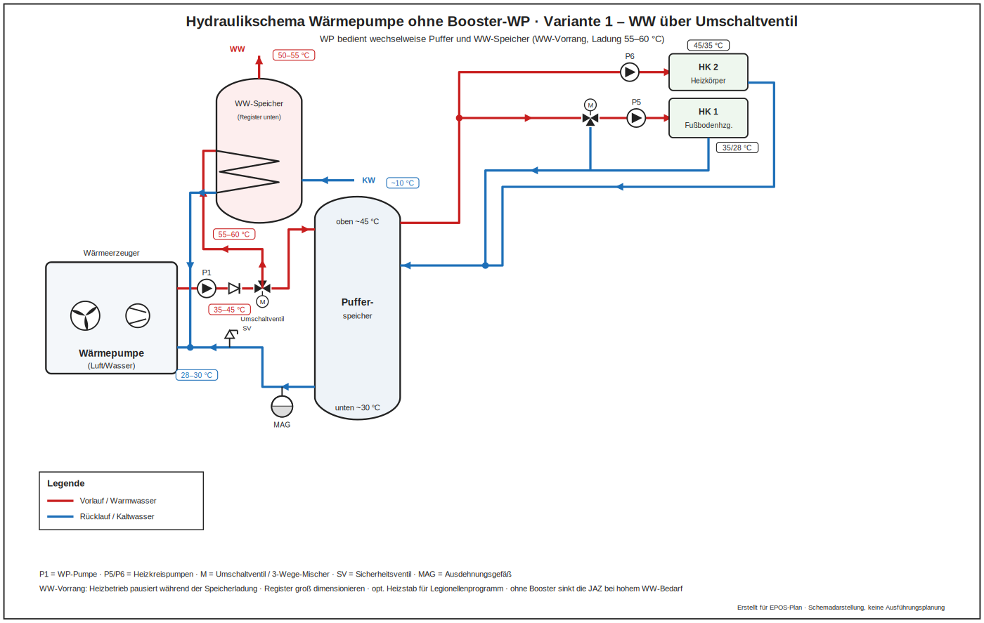
A single heat pump serves heating and hot water; a three-way valve switches between the heating circuit and the hot water cylinder. Simple and inexpensive, but the flow temperature during hot water charging determines the performance factor of the whole machine, and heating is interrupted while the cylinder is charged.
Advantages: simplest and cheapest arrangement with a single generator, little space, minimal control effort.
Drawbacks: Charging the cylinder interrupts space heating and forces the heat pump to a high flow temperature, which costs seasonal performance; the diverting valve is a wearing part.
Variant 2 – combined cylinder with fresh water station
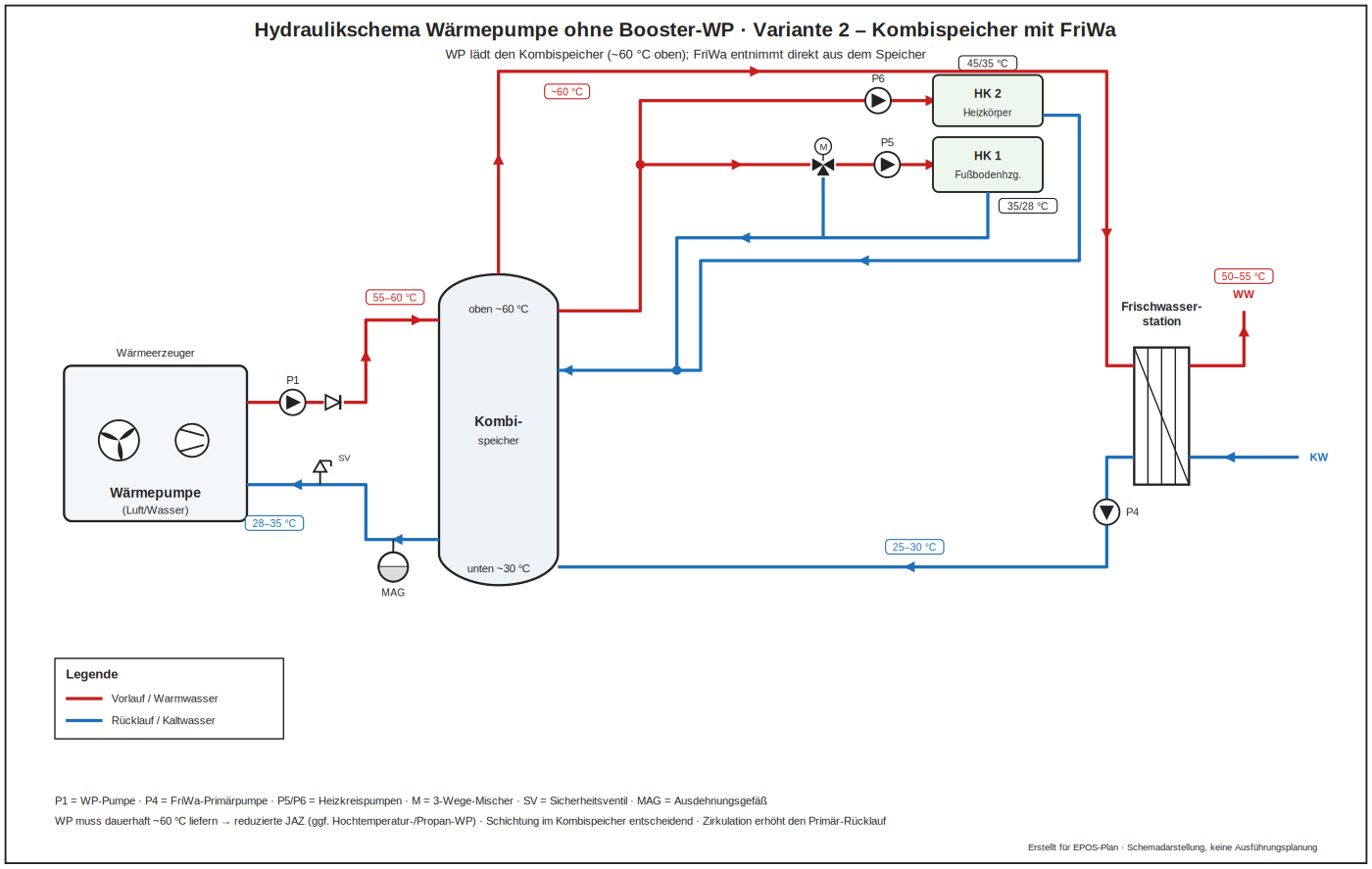
Heating and hot water are stored in one stratified cylinder; hot water is produced instantaneously in a plate heat exchanger. This keeps the stored volume free of drinking water and reduces legionella risk, but stratification must be protected, otherwise the heat pump sees an unnecessarily high return temperature.
Advantages: hygienically favourable because no large drinking water volume is stored; one cylinder for heating and hot water; stratification can be used deliberately.
Drawbacks: Stratification has to be protected; at high draw-off rates the fresh water station needs a high primary temperature, which lowers the performance factor; a larger store is required.
Variant 3 – buffer only for peak load, in a bypass
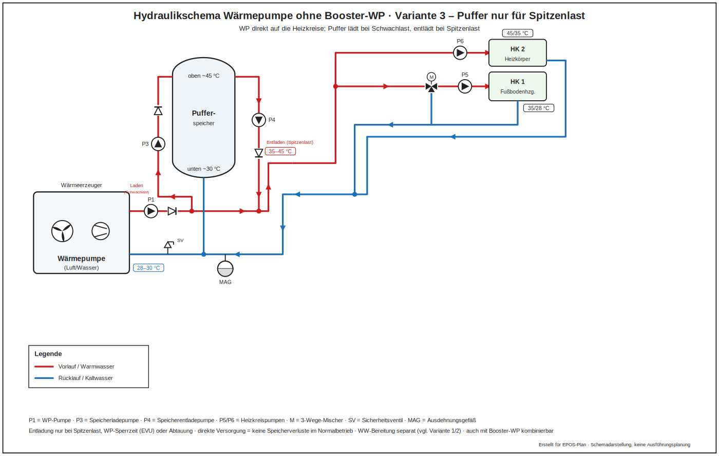
The heat pump feeds the heating circuits directly and only the peak load generator charges a buffer connected in a bypass. Cycling losses stay low and the flow temperature remains as low as possible; control is more demanding because two heat sources act on the same circuit.
Advantages: the heat pump works directly on the heating circuits at the lowest possible flow temperature, hardly any storage losses, high seasonal performance factor.
Drawbacks: More demanding control because two heat sources act on the same circuit; the buffer is only partly available; the minimum circulation rate has to be assured.
Heat pump with booster
Variant 1 – standard arrangement with heating circuits
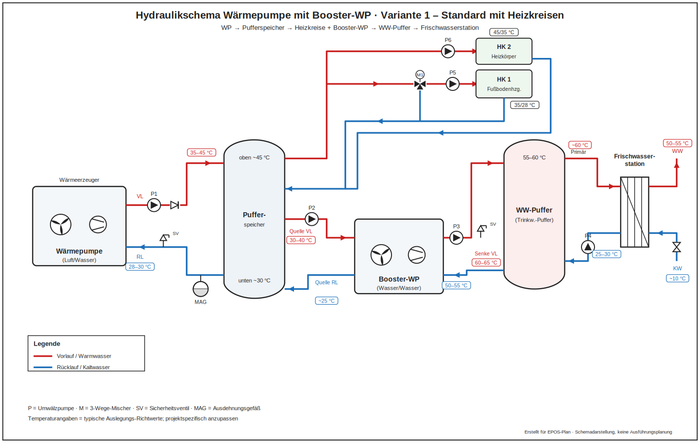
The base heat pump covers the space heating circuits at a low flow temperature; the booster heat pump raises the temperature for hot water only. This is the reference arrangement for the booster concept and gives the best seasonal performance factor in most projects.
Advantages: the reference arrangement of the booster concept: the base machine stays at a low flow temperature and the booster lifts only for hot water – in most projects the best seasonal performance factor.
Drawbacks: Two machines mean higher investment and more control effort; the source of the booster has to be clearly defined.
Variant 2 – hot water path only
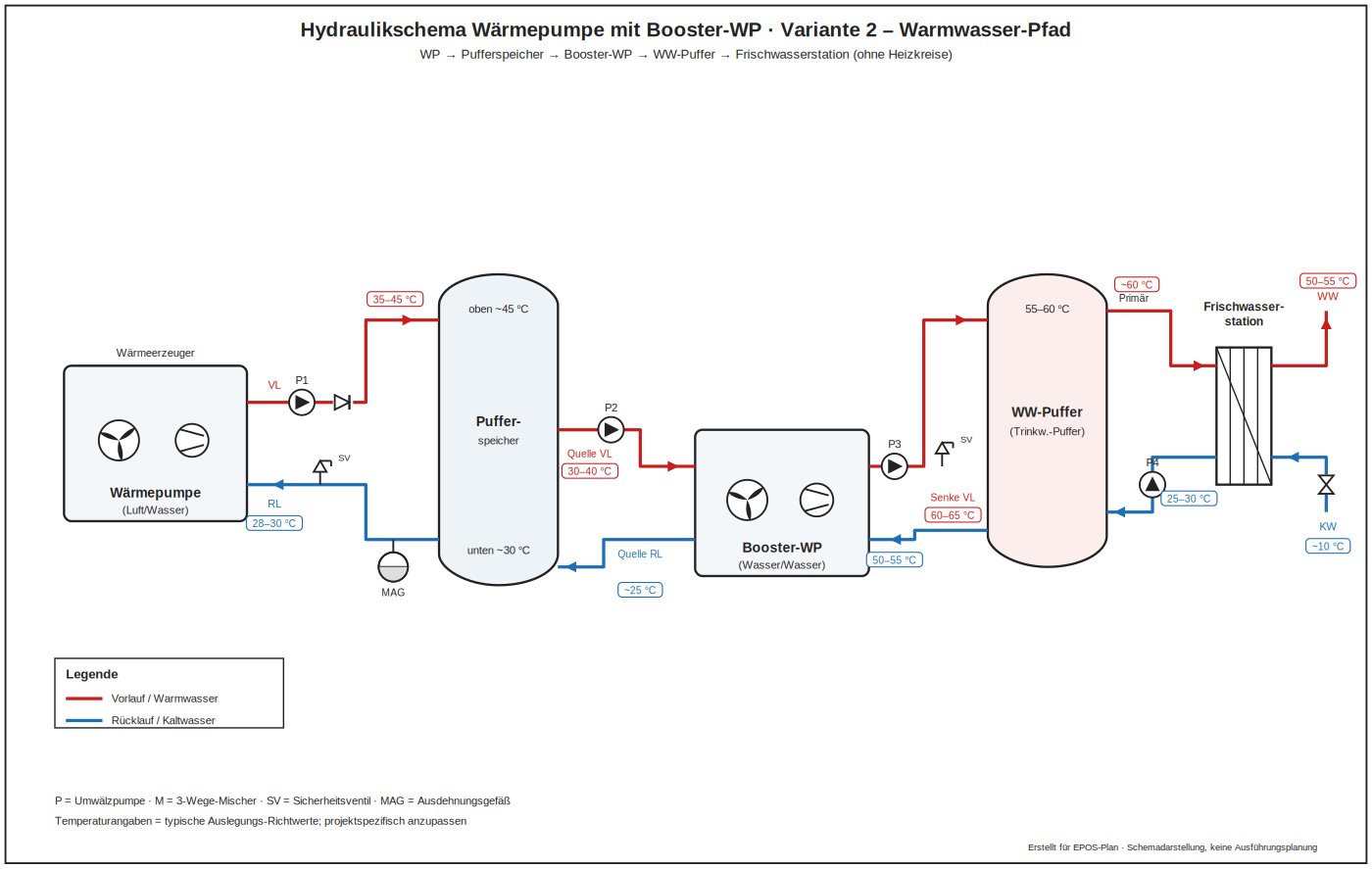
The booster works exclusively on the hot water cylinder while the base machine remains on the heating circuit. Suitable where hot water demand is high and constant, for example in hotels or care homes.
Advantages: ideal where hot water demand is high and steady, as in hotels or care homes; the heating circuit is unaffected by hot water operation.
Drawbacks: Only worthwhile with that kind of demand – otherwise the booster stands idle most of the time and the specific cost per kilowatt hour rises sharply.
Variant 3 – with circulation
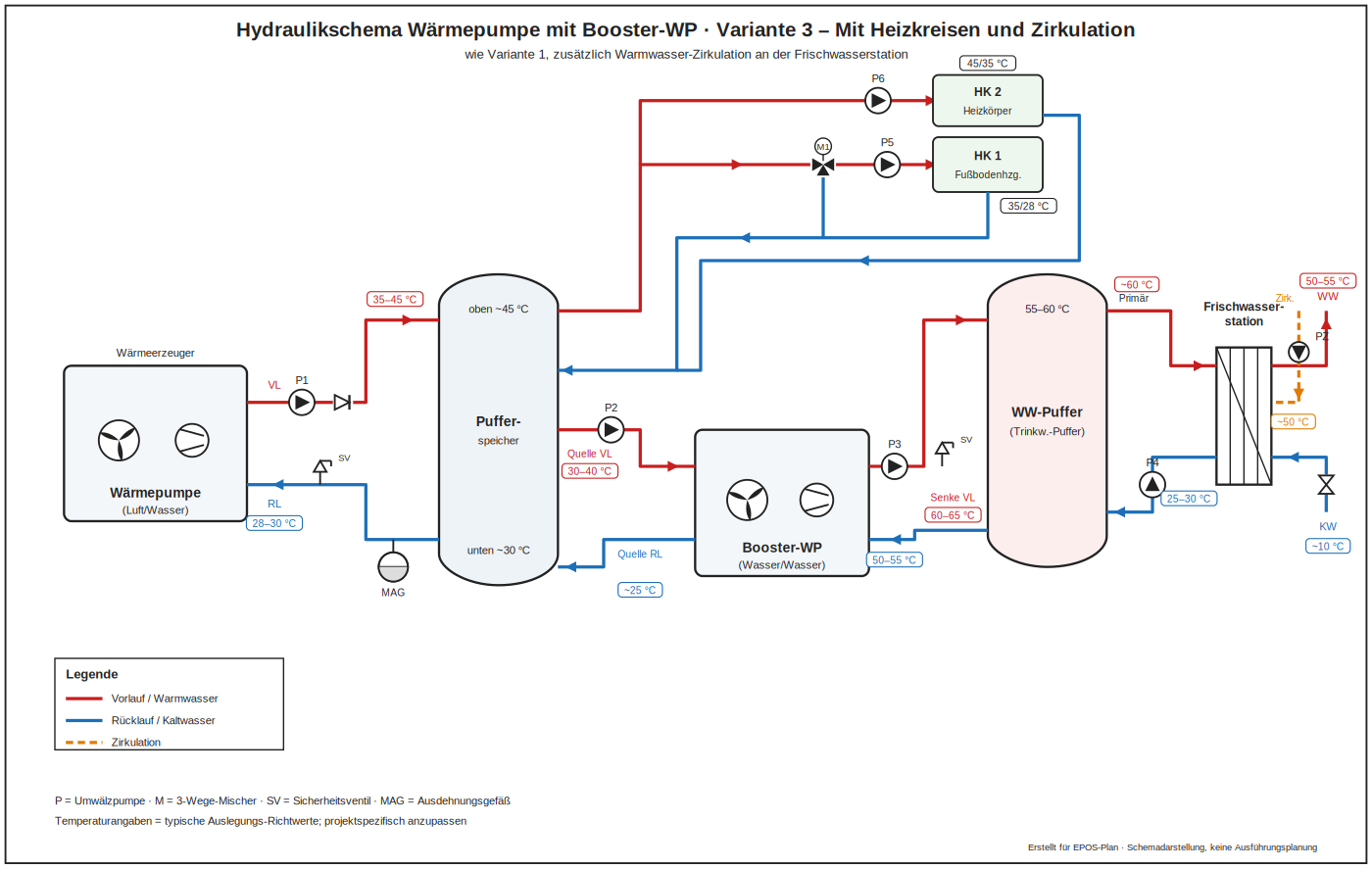
A circulation line keeps hot water available at every tap. Circulation losses can reach the order of the actual hot water demand in small buildings and must be entered explicitly, otherwise the calculation is optimistic.
Advantages: hot water is available instantly at every tap, high comfort and short waiting times.
Drawbacks: In small buildings the circulation losses easily reach the order of the useful hot water and have to be calculated explicitly; the booster runs more often as a result.
Variant 4 – with solar thermal
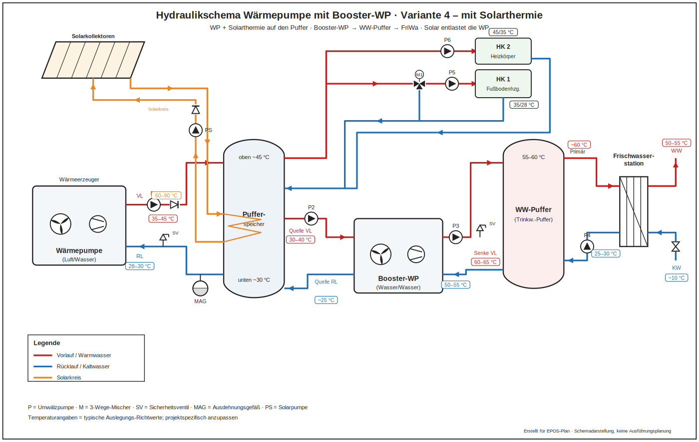
Solar collectors preheat the lower part of the cylinder; the booster only covers the remaining temperature lift. Yields are high in summer, and the heat pump running hours drop accordingly.
Advantages: high solar coverage in summer, the running hours of the booster drop noticeably.
Drawbacks: An additional circuit with its own stagnation behaviour and expansion vessel; the winter contribution stays small; without a priority rule the other generators heat away the solar zone.
Variant 5 – booster heat pump on the buffer store
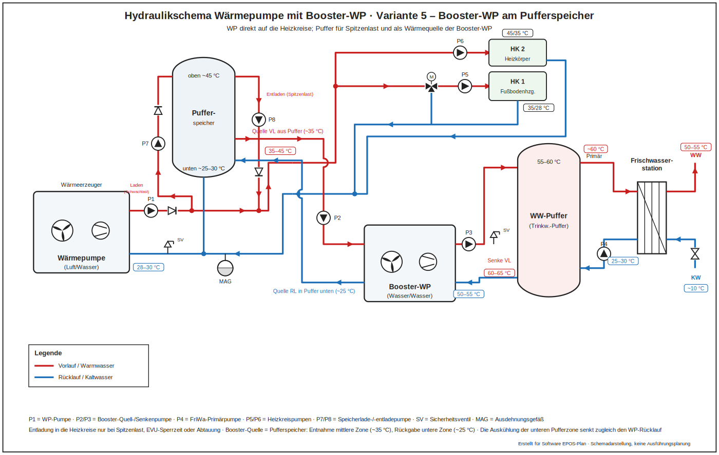
The main heat pump feeds the heating circuits directly while the buffer store serves two purposes at once: it holds heat for peak load and acts as the heat source of the booster heat pump. The booster draws its source water from the middle zone of the store at around 35 °C and returns it to the bottom at about 25 °C. Cooling the lower zone in this way also lowers the return temperature of the main heat pump and improves its performance factor, so the store works in both directions. It is discharged into the heating circuits only at peak load, during a utility lock-out period or while defrosting. In the simulation configuration this corresponds to the order heat pump before booster with a shared store assignment, the buffer being assigned to the booster as its heat source.
Advantages: the store works in both directions: peak load reserve and heat source for the booster; cooling the lower zone also lowers the return temperature of the main heat pump.
Drawbacks: Three heat sources on one store make this the most demanding control task; the minimum source temperature of the booster has to be assured at all times.
Variant 6 – cascade with booster and a 25 °C source inlet
In larger buildings several air-to-water heat pumps run as a cascade on a shared buffer store and cover the heating circuits with a 50/25 °C design. Domestic hot water is handled by a dedicated booster heat pump whose heat source is the heating return: it enters at 25 °C and leaves the circuit at 20 °C. The booster therefore cools the cascade return further, which raises the cascade performance factor – flow rate and minimum return temperature of the cascade have to be checked, and when the cascade is off, the minimum source temperature of the booster must still be assured. Hot water is stored in two buffers connected according to Tichelmann and prepared through a fresh water station; the circulation is returned into the cold side of the station, with the legionella cycle taken into account. Separate heat meters for heating, hot water and booster allow billing and monitoring.
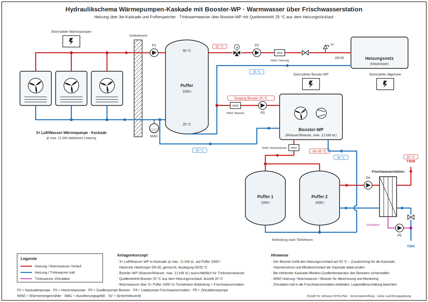
Advantages: scalable for larger buildings, the booster adds yield to the cascade by cooling the return to 20 °C, separate metering for billing and monitoring.
Drawbacks: Flow rate and minimum return temperature of the cascade need checking; with the cascade off, the source temperature of the booster must still be assured; three stores take up space.
Hybrid heat pump
A hybrid heat pump combines a heat pump and a condensing boiler in one plant. The heat pump covers the base load at moderate flow temperatures while the boiler takes peak load, very cold days or the high flow temperatures of existing buildings. That makes the combination particularly attractive in refurbishment, where the heat emitters stay in place at first and the heat pump share grows with every further insulation measure. The decisive questions are the bivalence or changeover point and whether the two generators work in parallel, alternately or in series.
Variant 1 – bivalent parallel with buffer store
Both generators charge the same stratified store at different heights: the heat pump the middle zone at 45 to 50 °C, the boiler the top at 65 to 70 °C. Below the bivalence point they run in parallel. This gives simple hydraulics and control, good running times for the heat pump and hot water through a fresh water station without a legionella cycle in the store. Bivalence point and release temperatures have to be parameterised carefully – otherwise the boiler cuts in too early and breaks the heat pump running times – and the boiler return should be taken from the lowest zone so that condensing operation is preserved. A low loss header is deliberately avoided; decoupling happens through the buffer.
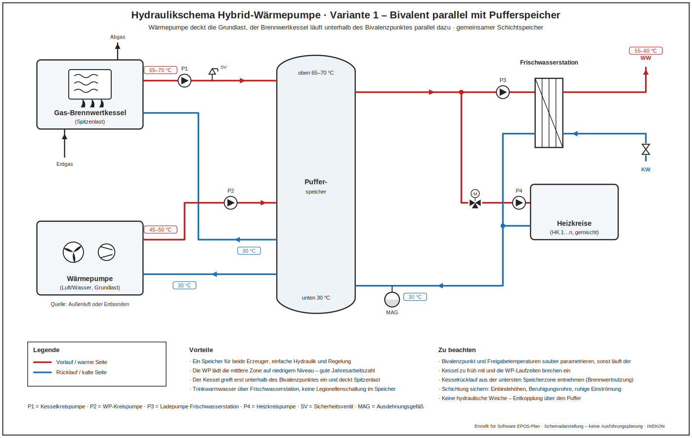
Advantages: one store for both generators, simple hydraulics and control, good running times for the heat pump, hot water through a fresh water station without a legionella cycle in the store.
Drawbacks: Bivalence point and release temperatures have to be parameterised carefully, otherwise the boiler runs too early; the boiler return must be taken from the lowest zone or the condensing benefit is lost; stratification has to be secured.
Variant 2 – bivalent alternate (changeover operation)
Below the changeover point the boiler works alone; a diverting valve in the flow and check valves in the returns separate the generators. The plant needs no buffer store, takes little space and is the inexpensive retrofit where an existing boiler is kept – which at the same time provides full redundancy for failure and servicing. Without a buffer, however, storage volume is missing: minimum circulation rate and cycling have to be checked and a series buffer in the return may be needed. The check valves are mandatory, otherwise water circulates through the idle generator. The chosen changeover point determines the gas share and therefore also eligibility for subsidies, and the defrost mode of the heat pump requires a controlled release of the boiler.
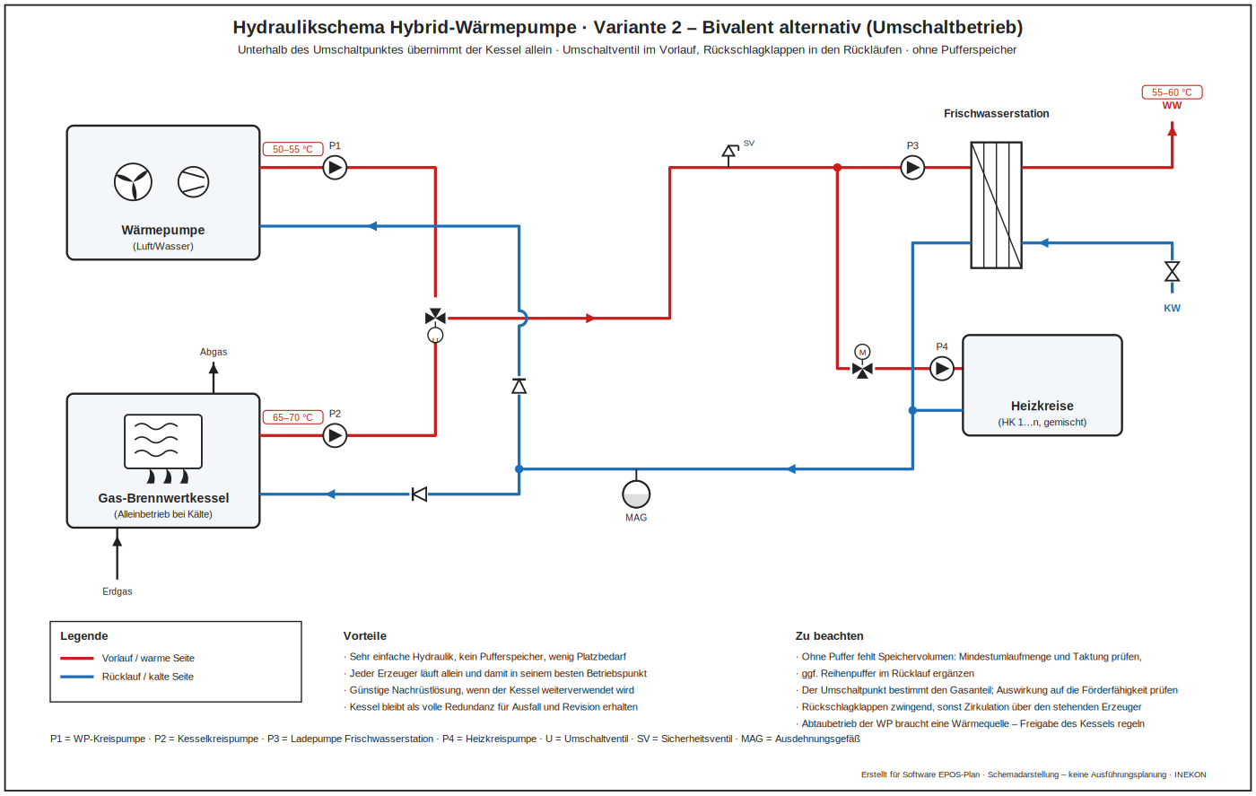
Advantages: very simple hydraulics without a buffer store, little space, inexpensive retrofit where a boiler already exists and remains available as full redundancy.
Drawbacks: Without a buffer there is no storage volume – check minimum circulation rate and cycling; check valves are mandatory; the changeover point determines the gas share and therefore eligibility for subsidies; the defrost mode needs a controlled boiler release.
Variant 3 – series connection with return temperature lift
The heat pump raises the heating return temperature and the condensing boiler tops it up to the set point. The heat pump therefore stays permanently at a low condensing temperature and reaches a high performance factor – even in existing buildings designed for 70 °C, without replacing the heat emitters. As demand falls through further refurbishment steps, the heat pump share grows by itself. A series connection means the same mass flow through both generators: flow rates and temperature spreads have to match and pressure drops add up. The boiler return temperature rises, which reduces the condensing benefit; a bypass is mandatory for summer operation, servicing and generator failure, and above roughly 55 °C return temperature the heat pump switches off.
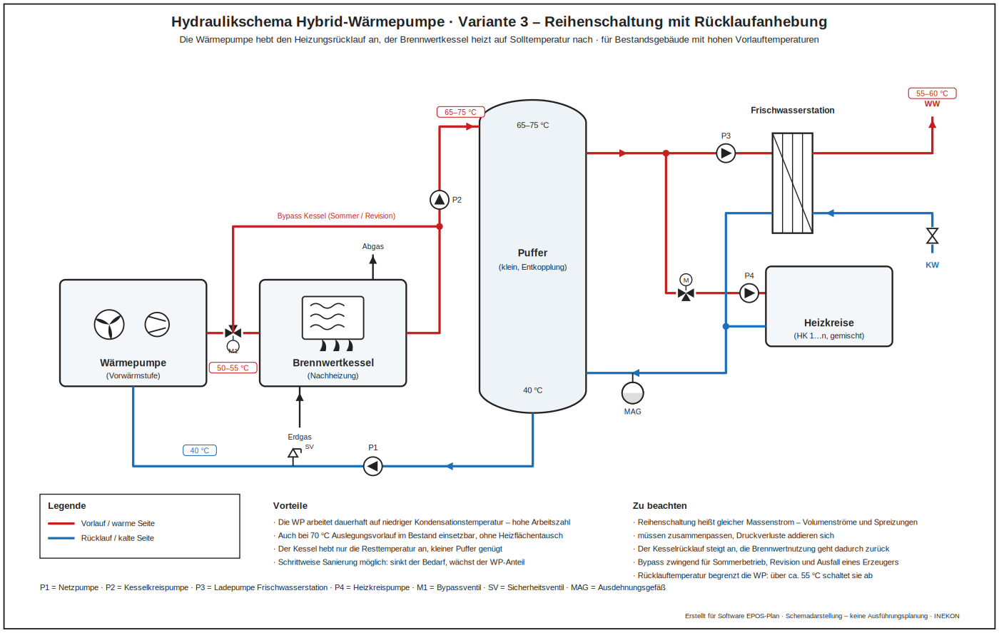
Advantages: the heat pump stays permanently at a low condensing temperature and reaches a high performance factor, even at a 70 °C design flow in existing buildings without replacing heat emitters; step-by-step refurbishment raises the heat pump share by itself.
Drawbacks: The same mass flow passes through both generators and pressure drops add up; the boiler return rises and reduces the condensing benefit; a bypass is mandatory; above roughly 55 °C return temperature the heat pump switches off.
Variant 4 – hybrid with solar thermal on a stratified store
Three generators work on one store, cleanly stratified by temperature level: solar thermal charges the lower zone, the heat pump the middle, the condensing boiler the top, with hot water taken through a fresh water station. The collectors therefore operate in the coldest range at their highest efficiency, and the solar yield simultaneously lowers the return temperature for heat pump and boiler. In summer the solar system covers domestic hot water largely on its own. The store volume has to be matched to the collector field – a guide value is 50 to 70 litres per square metre of aperture – and stagnation behaviour and the expansion vessel of the solar circuit need separate sizing. The control must give solar priority over heat pump and boiler, otherwise the generators heat away exactly the zone the collectors need: every recharge from below costs solar yield.
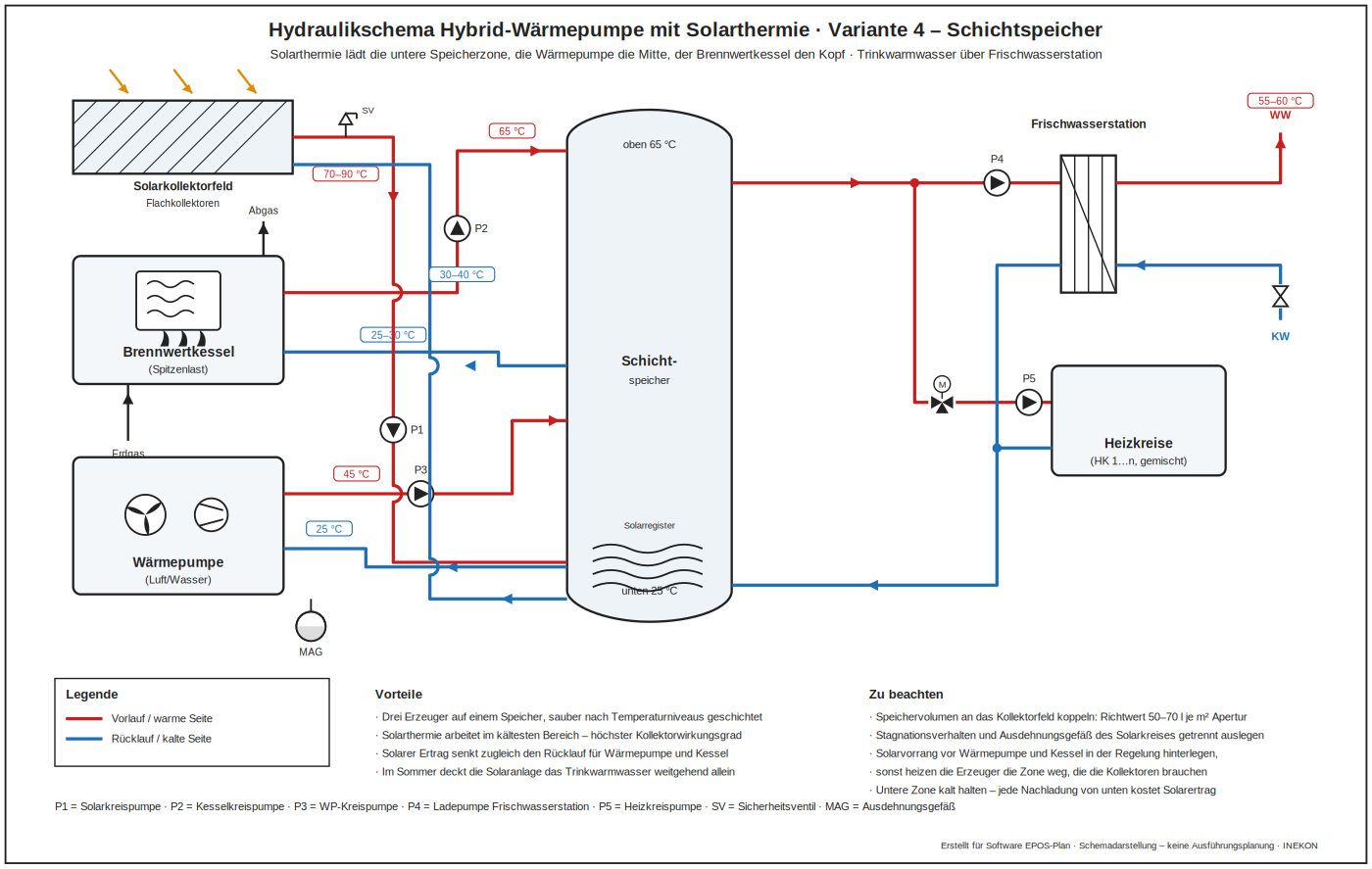
Advantages: three generators cleanly stratified by temperature level, the collectors work in the coldest range at their highest efficiency, and the solar yield lowers the return temperature for heat pump and boiler alike.
Drawbacks: The store volume has to be matched to the collector field (50 to 70 litres per square metre of aperture); stagnation behaviour and the expansion vessel of the solar circuit need separate sizing; without a solar priority rule the other generators heat away the lower zone.
Heat pump with CHP
Heat pumps and CHP units complement each other well but place opposite demands on the hydraulics. The CHP unit delivers high flow temperatures and needs the lowest possible return so that the engine heat is fully recovered; the heat pump, conversely, becomes more economical the lower the required temperature level stays. The four basic arrangements below differ mainly in how they separate these two temperature worlds. There is an electrical side as well: the electricity generated by the CHP unit can cover part of the heat pump demand, which raises self-consumption and lowers purchase cost.
Variant 1 – parallel on a shared buffer store
Both generators feed the same buffer store, but different zones: the CHP unit charges the top at 75 to 80 °C, the heat pump feeds the middle zone at 50 to 55 °C, and the common return is drawn from the bottom. The decoupling is deliberately done through the store rather than a low loss header – a header allows crossflow and thereby raises the CHP return temperature, which reduces the heat recovered from the engine. The electrical link from the CHP unit to the heat pump is shown as a dashed line.
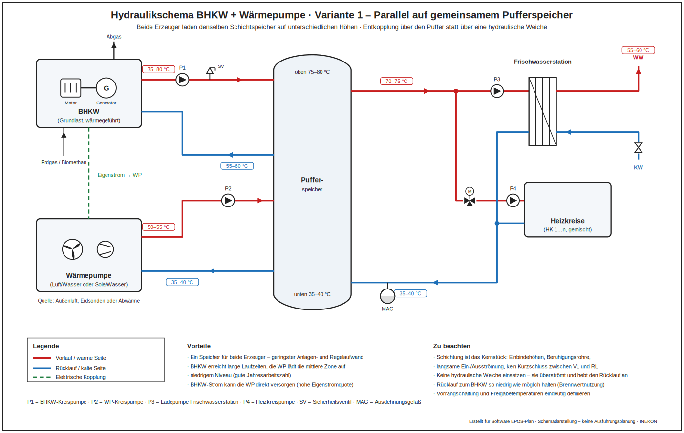
Advantages: one store for both generators, the lowest plant and control effort, long CHP running times, and the CHP electricity can supply the heat pump directly.
Drawbacks: Stratification is the crux – connection heights, calming pipes and gentle inflow decide the outcome; do not use a low loss header; keep the CHP return as low as possible; define the priority logic unambiguously.
Variant 2 – series connection
The heat pump acts as the preheating stage from 40 to 55 °C, the CHP unit then raises the temperature to 80 °C. This gives the best seasonal performance factor because the heat pump stays within its favourable temperature range throughout. The price is a common mass flow through both generators and a CHP return temperature that rises with the preheating. A bypass with a three-way valve is provided so that summer operation and servicing of one generator are possible without shutting down the whole plant.
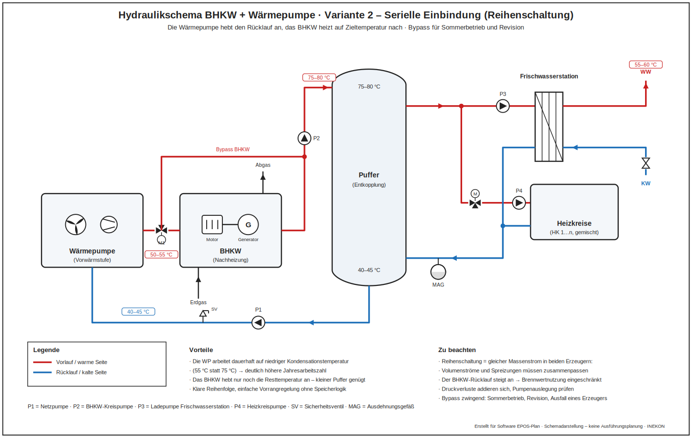
Advantages: the heat pump works at 55 instead of 75 °C and therefore reaches a markedly higher seasonal performance factor.
Drawbacks: Both generators carry the same mass flow; the CHP return rises with the preheating and reduces the heat recovered from the engine; a bypass for summer operation and servicing is required.
Variant 3 – temperature separation with two stores
Instead of a shared store the generators work on separate circuits: the CHP unit supplies the high-temperature buffer for radiators and the fresh water station, the heat pump the low-temperature buffer for underfloor heating. The returns stay separate so that each generator keeps its own temperature level. Hydraulically this is the cleanest solution wherever different heat emitters or new and existing building sections come together. A connecting pipe between the two stores is provided purely as isolated redundancy.
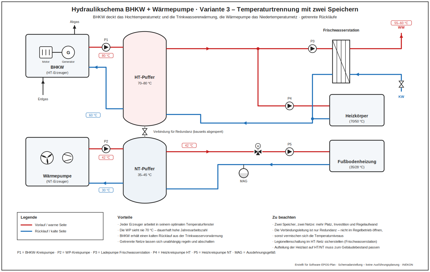
Advantages: each generator works in its optimum temperature window, the heat pump never sees 70 °C – a permanently high seasonal performance factor.
Drawbacks: Two stores and two networks mean more space, investment and control effort; the returns have to stay strictly separate or the advantage is lost.
Variant 4 – CHP exhaust heat as the heat pump source
An exhaust gas heat exchanger cools the flue gas down to around 35 °C and an intermediate circuit feeds the evaporator of the heat pump with it. This yields the highest fuel utilisation because the condensation heat of the flue gas is recovered as well. Two conditions apply: the heat pump depends on the CHP unit running – without engine operation there is no source – and the chimney has to be built to withstand condensate.
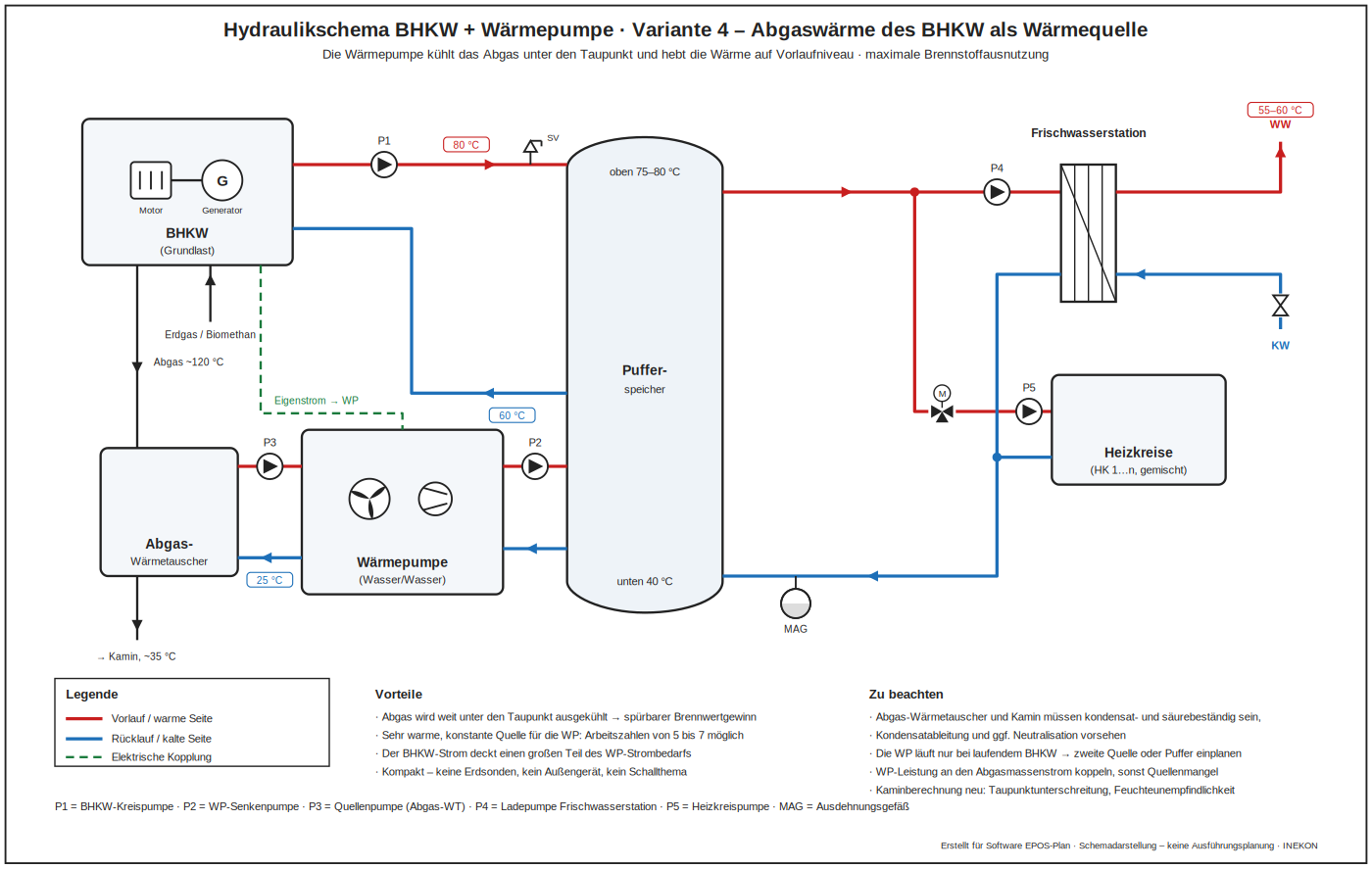
Advantages: the flue gas is cooled far below its dew point – a noticeable condensing gain and a very warm, constant source for the heat pump with performance factors of 5 to 7.
Drawbacks: The heat pump depends on the CHP running – no engine operation, no source; the chimney has to withstand condensate; an exhaust gas heat exchanger and condensate drainage are added.
Solar thermal with heat pump
Solar thermal systems and heat pumps go together well, but hydraulically they easily compete for the same part of the store. A heat pump works the more efficiently the smaller the gap between source and target temperature, which is why the flow temperature is kept as low as possible through generously sized heat exchanger surfaces. The solar system, by contrast, delivers its heat when the sun shines and at a temperature that cannot be chosen freely. Where a utility lock-out period is involved, one buffer store has to do two jobs at once: bridge the lock-out and absorb the solar heat. The four arrangements below show how to organise that.
Variant 1 – domestic hot water with a heat pump cylinder
For bivalent operation a cylinder with a very large internal heat exchanger is used, reserved exclusively for the heat pump – only then does the required flow temperature, and with it the performance factor, stay low. The solar system charges the same cylinder through an external heat exchanger, because a second internal coil would reduce the usable surface and disturb stratification. In summer the collectors cover most of the hot water demand on their own and the heat pump only tops up occasionally. Drinking water hygiene requirements and a sufficiently large transfer area in the external heat exchanger need attention.
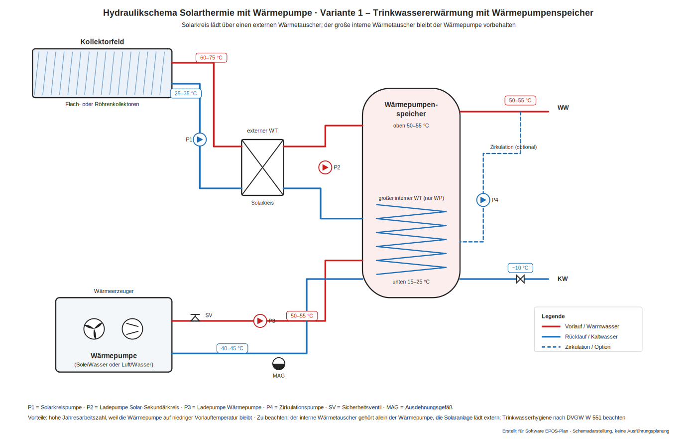
Advantages: in summer the solar system covers hot water largely on its own while the heat pump stays at a low flow temperature and thus a high performance factor.
Drawbacks: The internal heat exchanger is reserved for the heat pump, so the solar system needs an external heat exchanger with its own pump; drinking water hygiene requirements apply.
Variant 2 – heating support on a shared buffer store
Heat pumps are often subject to lock-out periods imposed by the grid operator and therefore need a heating-water buffer store anyway. That store lends itself to solar charging as well, which keeps the installation effort low. The catch lies in the timing: lock-out periods usually fall during the day, exactly when the solar system delivers – so the charging times before them are contested, which can be eased by the control strategy but not eliminated. The solar system therefore charges the middle zone through an external heat exchanger while the heat pump occupies the upper part.
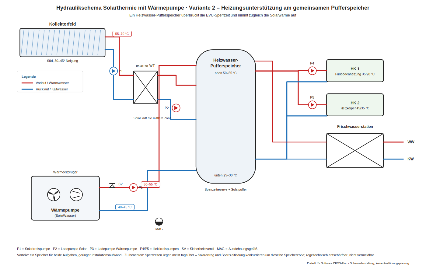
Advantages: one store fulfils both tasks – bridging the lock-out period and absorbing solar heat – and the installation effort stays low.
Drawbacks: Lock-out periods usually fall during the day, so solar yield and lock-out charging compete for the same zone; the control can ease this but not remove it, and the achievable solar fraction stays limited.
Variant 3 – separate zones for lock-out reserve and solar heat
Where a higher solar fraction is wanted, the buffer store is enlarged. The share needed to bridge the lock-out period then has to be made available to the heat pump separately, both hydraulically and in terms of control – otherwise no reserve is left at the decisive moment. In practice this leads to two stores, or to one store with clearly separated sections: the lock-out reserve of the heat pump on top, the solar-charged part below it raising the return temperature of the heating circuits. A connection between the two makes sense only as isolated redundancy. If the heat pump does not strictly require a buffer store, the solar store is sized exactly as it would be in combination with a boiler.
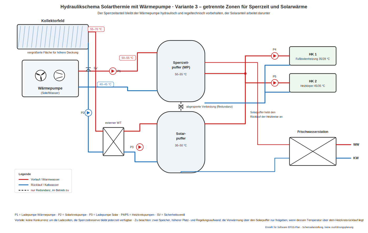
Advantages: no competition for charging times, the lock-out reserve is available at all times, and the solar fraction can be raised considerably through the additional volume.
Drawbacks: Two stores or clearly separated sections mean more space, investment and control effort; preheating may only be released when the solar temperature exceeds the heating return.
Variant 4 – solar heat as the source and ground regeneration
Instead of going into the store, the solar heat can be fed to the source side. At low collector temperatures – with unglazed collectors or PVT modules, for instance – it raises the brine inlet temperature and improves the coefficient of performance directly; in summer the surplus recharges the borehole field and counteracts its long-term cooling. A changeover decides, based on collector temperature, whether the heat goes into the store or into the brine circuit. Frost protection in the collector circuit, a heat exchanger between the solar and brine circuits and agreement with the permit for the borehole field all need attention.

Advantages: solar heat is usable even at low collector temperatures, it raises the source temperature and recharges the borehole field in summer – the seasonal performance factor rises noticeably.
Drawbacks: Frost protection in the collector circuit and a heat exchanger to the brine circuit are required, the regeneration has to be agreed with the borehole permit, and there is no direct contribution to charging the store.
Combinations with special properties
The previous sections show the classic generator combinations. The four schemes below go beyond them: each unlocks a property the standard solutions cannot reach – the electrical side as part of the heat plan, a heat source without drilling, a network that carries heat and cold at the same time, and the use of existing waste heat. All of them can be modelled in EPOS-Plan and pay off precisely where the usual concepts reach a limit.
K1 – heat pump with photovoltaics, battery storage and power-to-heat
Special advantage: the electrical side is planned together with the heat. The heat pump runs in a PV-optimised mode and raises its output exactly when a surplus is available; the buffer store is deliberately charged beyond its set point and carries the evening hours without drawing from the grid. An immersion heater absorbs surplus peaks that neither the battery nor the heat pump can use. PV array, battery and heat generator become one system instead of three separate trades – with markedly higher self-consumption and capped purchase peaks.
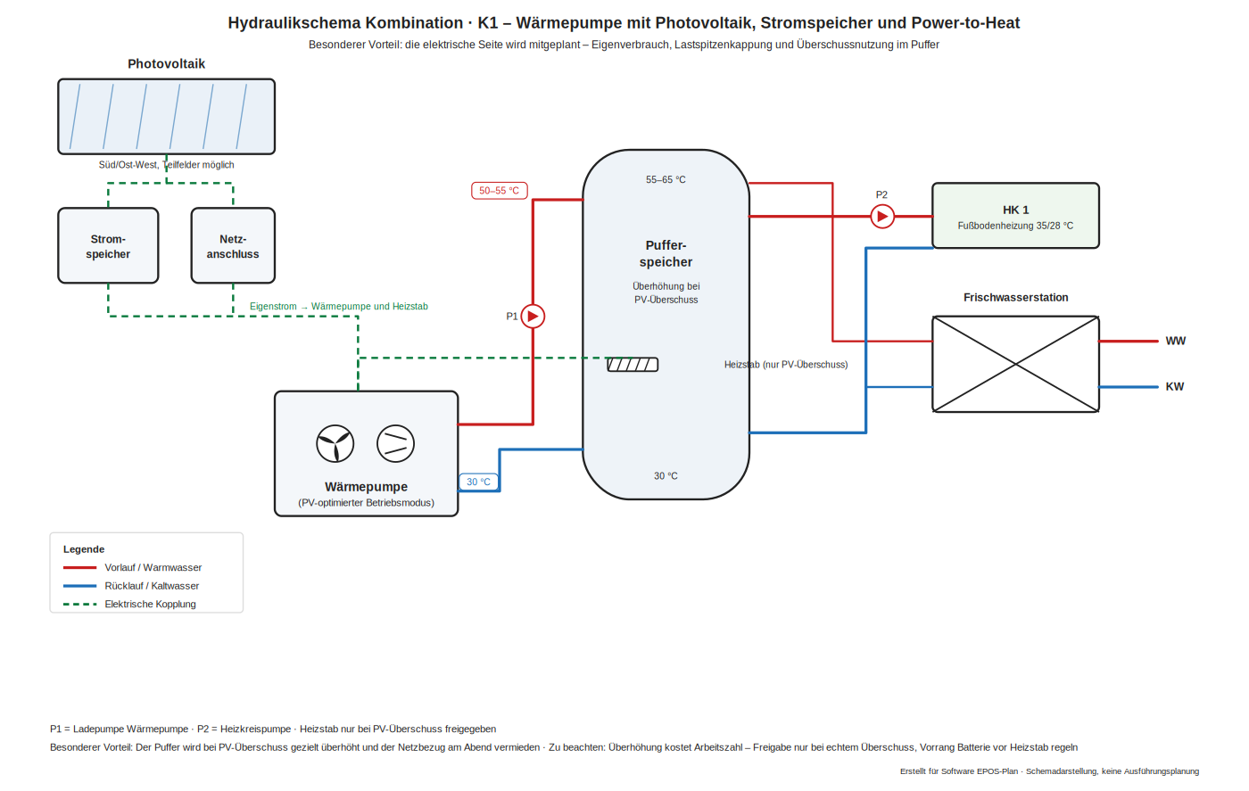
Advantages: self-consumption and self-sufficiency rise substantially, the peak grid load falls, and the store becomes a thermal electricity store at no extra investment.
Drawbacks: Overcharging the buffer costs performance factor and standing losses – it may only be released on a genuine surplus; the battery should be served before the immersion heater, and the control needs a reliable surplus forecast.
K2 – ice store with a solar air absorber as heat source
Special advantage: a heat source without drilling and without a water permit. An unglazed absorber on the roof uses both irradiance and ambient air and charges a cistern in the ground. Once that cools to zero degrees, the phase change delivers around 93 watt hours per litre – plenty of capacity exactly when it is cold outside and an air source heat pump struggles. In summer the frozen store provides passive cooling and regenerates itself in the process.
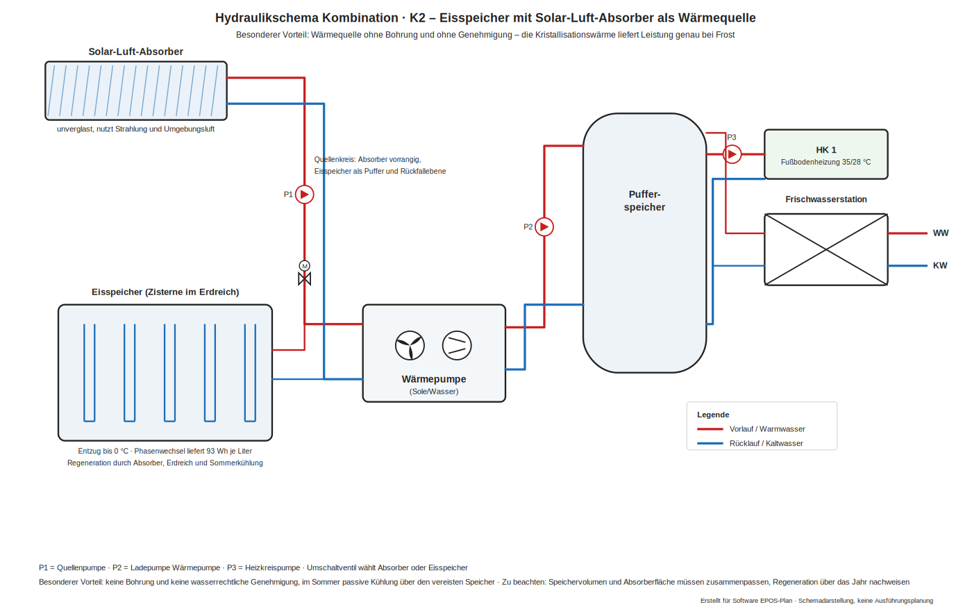
Advantages: permit-free and usable where boreholes are impossible; the source temperature stays stable in winter and passive cooling needs no additional machine.
Drawbacks: Store volume and absorber area have to be matched, the annual regeneration has to be demonstrated, and excavation, structural design and space requirement of the cistern are considerable.
K3 – cold district heating with decentralised heat pumps
Special advantage: one network for heat and cold at the same time. Instead of distributing hot water, an anergy network at 5 to 20 °C carries the source to the buildings, and each building lifts it to its own temperature level with its own heat pump. Because the network is barely warmer than the ground, insulation and network losses almost disappear, and every building decides its own flow temperature and hot water concept. When a building cools in summer it feeds the waste heat back – the cooling of one becomes the source of the other.
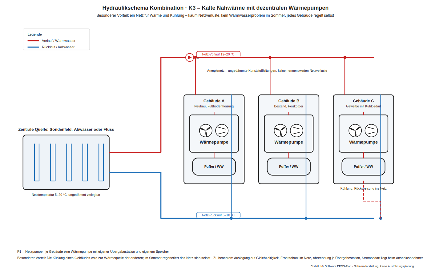
Advantages: virtually no network losses, no legionella issue in the network, mixed building standards are possible, and summer cooling regenerates the source.
Drawbacks: Higher investment in the network and the transfer stations, the electricity demand shifts to the connected customer, coincidence and frost protection have to be considered in the design, and billing becomes more involved.
K4 – waste heat from refrigeration or a process as heat source
Special advantage: cooling and heating at the same time. Wherever cooling is needed anyway – server room, cold store, compressed air, injection moulding, dairy – condenser waste heat arises at 25 to 35 °C and is usually destroyed in a dry cooler. As the source of a water-to-water heat pump it is warm, constant and free of charge; performance factors of 5 to 7 are achievable. At the same time the refrigeration plant benefits from a better condensing temperature and the dry cooler remains only as emergency cooling.

Advantages: a very high performance factor from a free source available all year; the refrigeration plant saves rejection energy and both sides share the payback.
Drawbacks: Heat and cooling demand have to coincide in time – otherwise the source stays unused or is missing; emergency cooling has to be provided, and the refrigeration and heating circuits should be separated hydraulically because of glycol and operational safety.
CHP unit with peak load boiler
Scheme 1 – parallel connection through the buffer
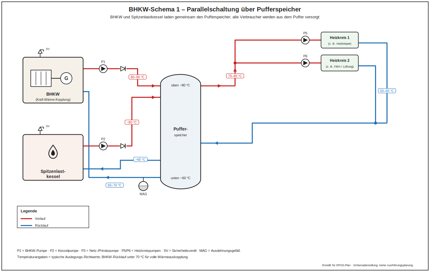
CHP unit and boiler both feed the buffer store in parallel. The CHP unit runs long and evenly, the boiler covers peaks. The most common and most robust arrangement.
Advantages: the most robust and most common arrangement: the CHP unit runs long and evenly, the boiler covers the peaks, and the control stays manageable.
Drawbacks: The store needs space, and connection heights and stratification decide the running times actually achieved.
Scheme 2 – CHP with buffer, boiler connected directly
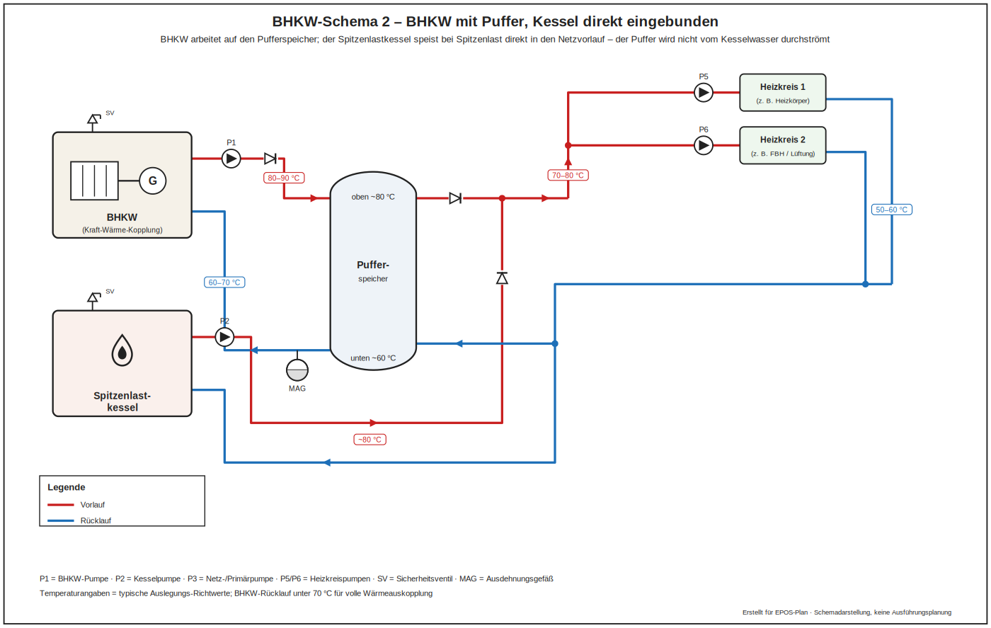
The CHP unit charges the buffer while the boiler feeds the distribution circuit directly. The boiler reacts quickly to sudden demand without cooling the store.
Advantages: the boiler responds immediately to sudden demand without cooling the store.
Drawbacks: Two feed-in points raise the control effort; the boiler can lift the common return temperature and thus impair the heat recovered from the CHP unit.
Scheme 3 – series connection with the boiler as a second stage
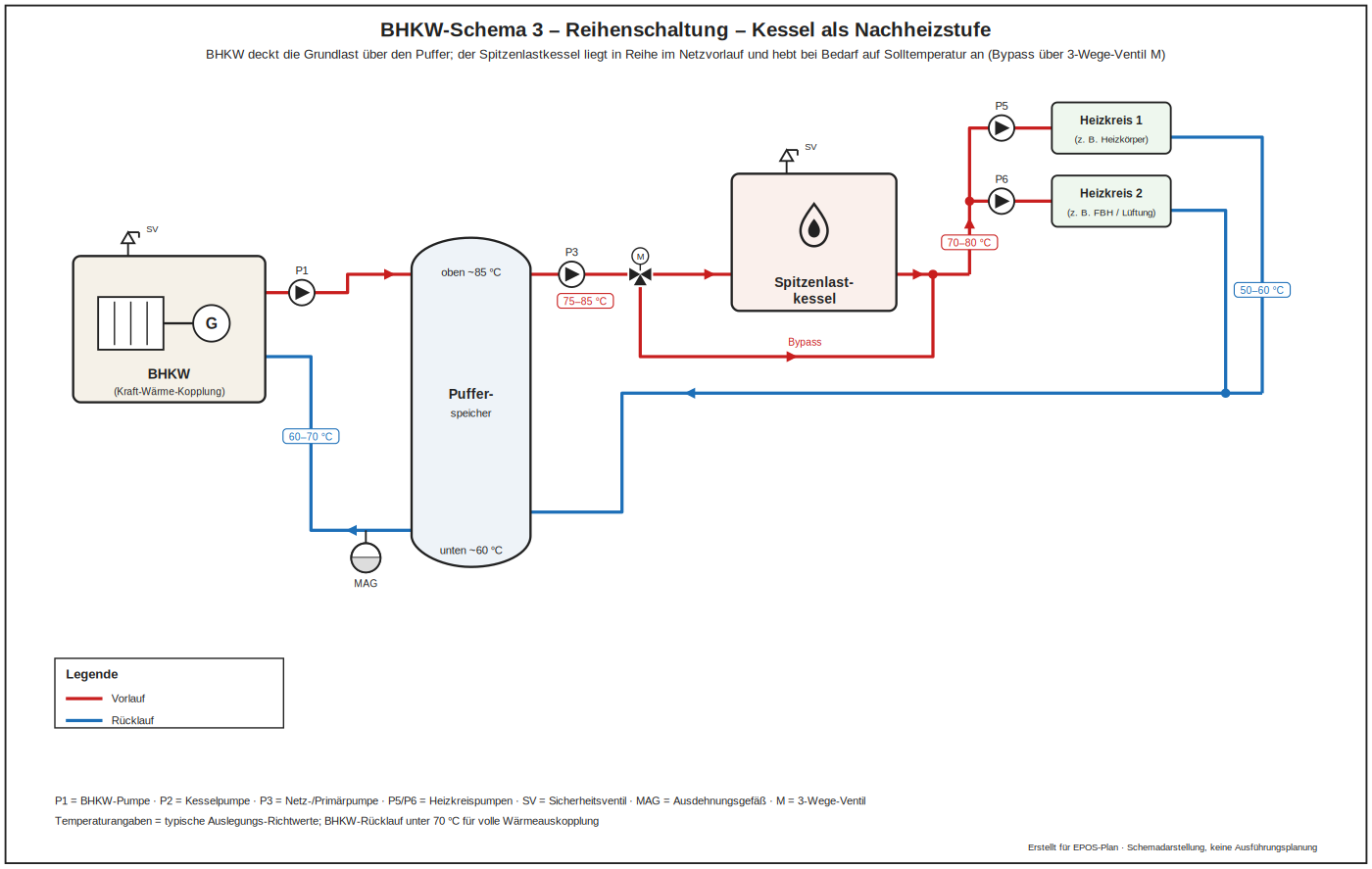
The boiler raises the CHP flow temperature when required. Return temperature to the CHP unit stays low, which suits condensing operation, but the boiler operates at part load frequently.
Advantages: the return to the CHP unit stays low, which suits both heat recovery and condensing operation.
Drawbacks: The boiler often works at part load; both generators carry the same mass flow and the pressure drops add up.
Scheme 4 – integration through a low loss header
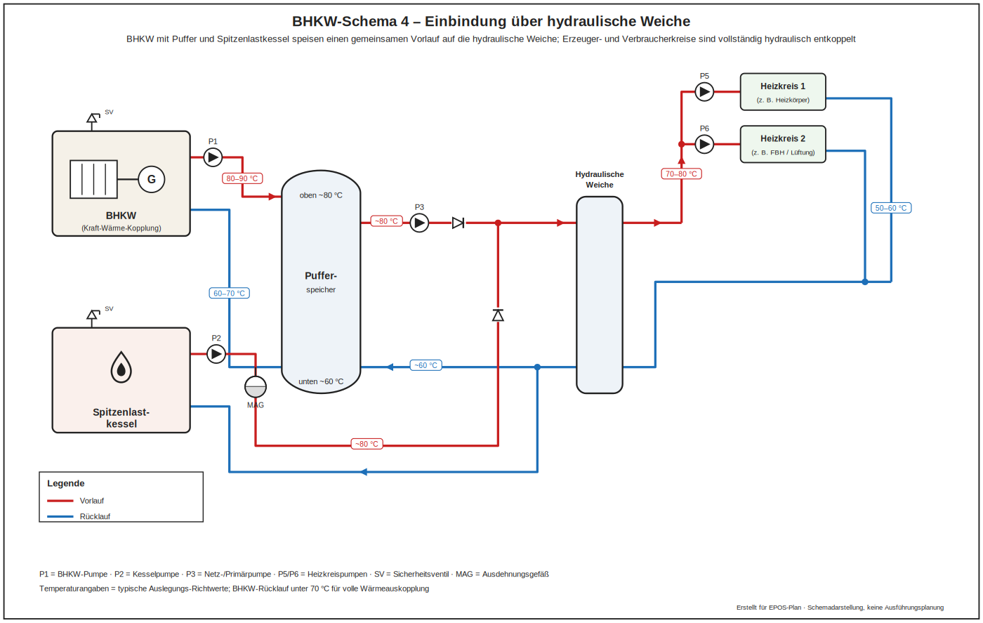
A low loss header decouples generator and distribution circuits hydraulically. Commissioning is simple; mixing in the header raises the return temperature and must be accepted in the calculation.
Advantages: generator and distribution circuits are cleanly decoupled and commissioning is simple and tolerant of flow rate errors.
Drawbacks: Mixing in the header raises the return temperature and costs heat recovery – for CHP plants the essential drawback of this solution.
Scheme 5 – series connection without a buffer
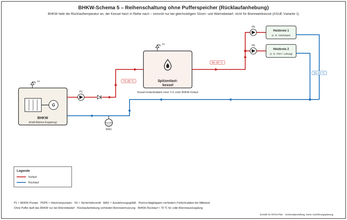
Used where space is unavailable. The CHP unit follows demand directly and therefore cycles; only advisable with a modulating unit and stable base load.
Advantages: minimum space requirement, lowest investment, no storage losses.
Drawbacks: The CHP unit follows demand directly and cycles; only defensible with a modulating unit and a stable base load.
Scheme 6 – parallel connection without a buffer
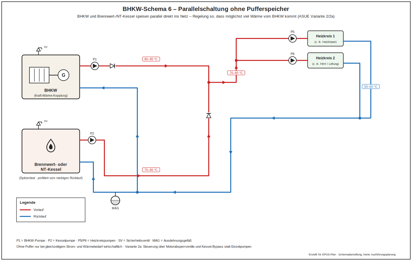
Both generators feed the distribution circuit in parallel. Simple, but neither generator is protected against short cycling.
Advantages: the simplest hydraulics, both generators feed the distribution circuit directly.
Drawbacks: Neither the CHP unit nor the boiler is protected against short cycles; full load hours regularly fall short of the design figure.
Scheme 7 – switching via valves
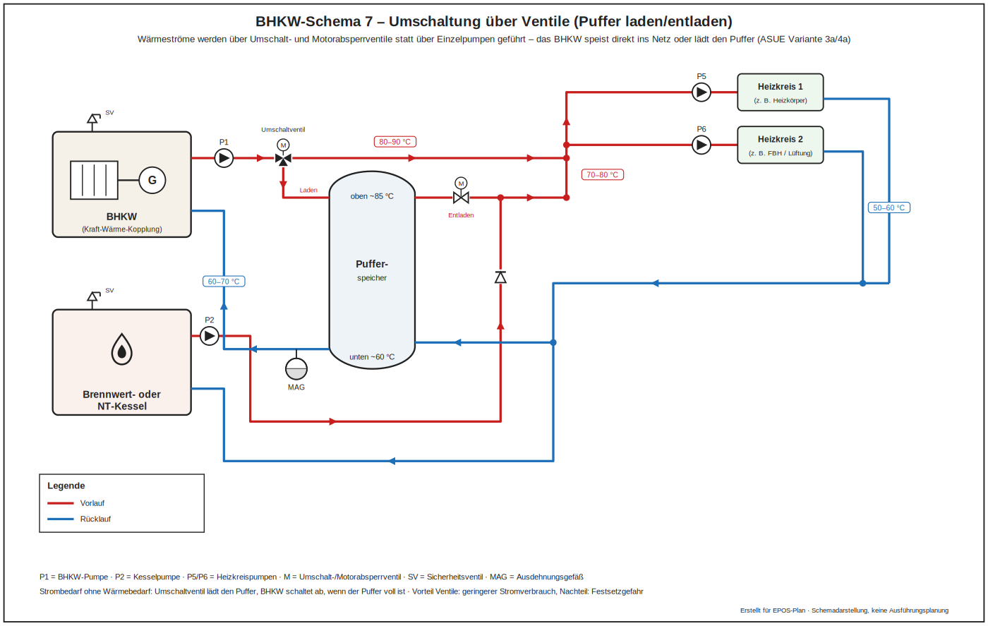
Valves route the flow either through the CHP unit or through the boiler. Clear operating states, but the control logic has to handle transitions carefully to avoid pressure surges.
Advantages: clearly defined operating states and an unambiguous assignment of the generators.
Drawbacks: The control logic has to handle the transitions cleanly, otherwise pressure surges occur; the valves are wearing parts and belong in the maintenance schedule.
Scheme 8 – buffer in a bypass with dedicated pumps
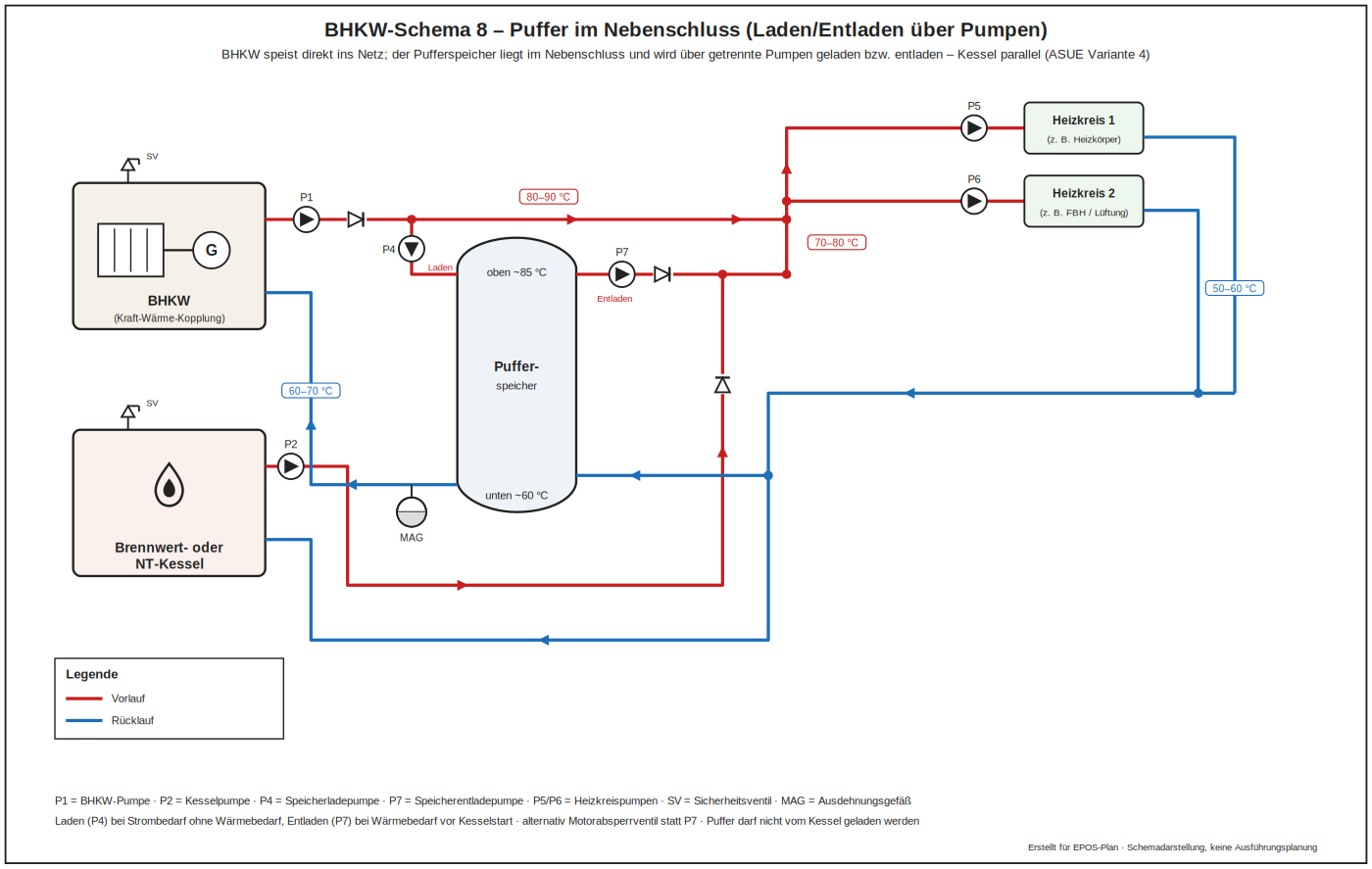
The buffer sits in a bypass with its own charging and discharging pumps. Charging and discharging are fully decoupled, allowing deliberate stratification management.
Advantages: charging and discharging are fully decoupled and stratification can be managed deliberately.
Drawbacks: Two additional pumps mean more auxiliary energy, more control effort and additional sources of failure.
Scheme 9 – practical example of an existing plant
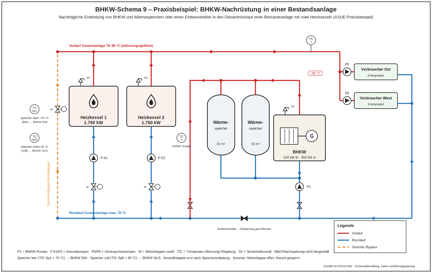
A retrofit situation: an existing boiler stays in place, the CHP unit is added on the return side. Typical for refurbishment projects where the existing hydraulics cannot be changed completely.
Advantages: uses the existing hydraulics, low investment and quick to implement during operation.
Drawbacks: Compromises on return temperature and running time are unavoidable; the outcome depends heavily on what is found on site and should be calculated beforehand.
Scheme 10 – extension with solar thermal
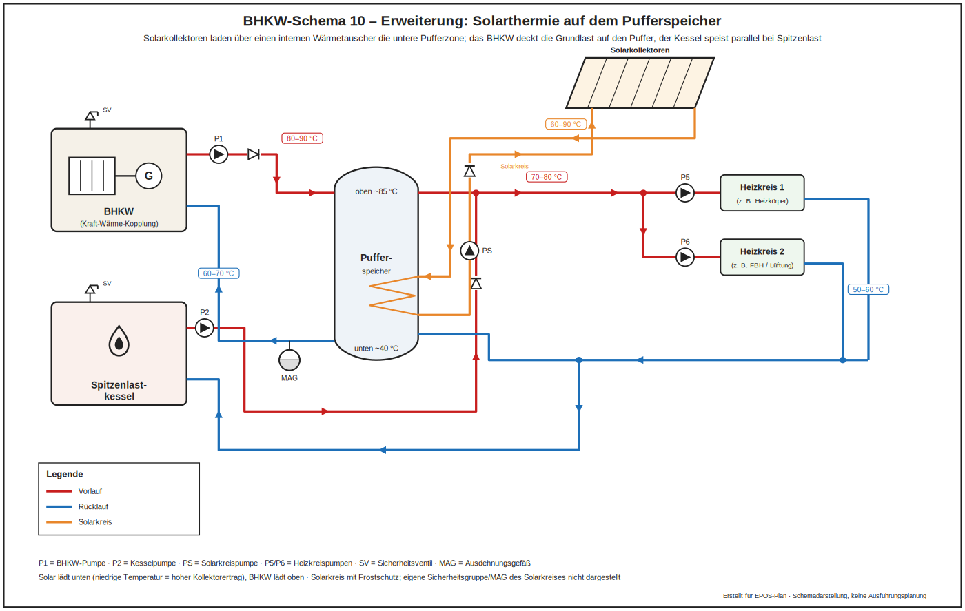
Solar collectors are added to the CHP and boiler arrangement and charge the lower part of the buffer. Summer operation of the CHP unit is reduced, which must be checked against its full load hours.
Advantages: an additional renewable share that relieves the boiler in summer and lowers fuel cost.
Drawbacks: Summer operation of the CHP unit is displaced – the full load hours have to be checked; without a priority rule the solar system and the CHP unit compete for the same zone of the store.